Wednesday, March 28, 2018

Yaesu FT-847 432MHz driver module repair

Recently my friend Henrik OZ8ZS asked me to look into his "turbo" FT-847 because of intermittent power output on 70cm.

Websites are full with similar malfunctions in this "ol' good" rig caused
by deteriorate solder around PIN switching diodes in PA, both 2m and 70cm (see article by Peter OZ1PIF).
But there could be another cause - few OM's reported it before and some of them bring the radio back to full functionality after repair - see 2m module repair by OK2KKW guys http://www.ok2kkw.com/zzz/ft847_pa_failure.htm
This time 70cm module suffered from overheating, or (my personal thoughts ) mechanical and/or temperature stresses, after long period of use. Will back to this "probable" cause at the end.

Of course this issue can be repaired by replacing original module with Mitsubishi M67799M/A module -with no additional tuning needed. 

If You are not skilled enough with ROHS soldering just don't do it. 
These legs are very fragile and thin, module can be damaged easily.

Let's start - first we need to remove zillion of screws around PCB, 4 smaller screws around 2m & 70cm models also - do not use excessive force, they are glued - use good philips screwdriver instead.


After removing the PCB it's obvious that Yaesu did not use much "very expensive" beryllium thermo paste under transistors at factory stage :-), nevertheless, we will remove old, dry fluid and apply fresh one later.

Just after desoldering first two legs the become loose, and popped somewhere. Actually they gone inside the module :-) input and output legs were still "soldered" in module. Let's see how Mitsubishi PF0340a looks inside...
 
That's it - opening the case with small screwdriver revealed the mystery of intermittent power - two legs - power supply and bias were completely away, looking closer to their solder pads we can see completely damaged soldering points, they are grey and absolutely not OK.

Let's prepare to the module to repair job - find some bright place on your workbench, magnifying glasses and temperature controlled soldering station, good "Silver" ROHS solder will help the job much.
For the job prapared small piece of unused PCB and double sided tape to secure the module right in place, and avoid accidental move when soldering.


Now ceramic module pad and the legs are on same level as "help" PCB.


 And voila! This is the module after soldering - all 4 of legs were soldered again, just in case.

Now I will back for a moment to "mechanical stress" mentioned at the start...
Bearing in mind that only two of 4 legs were detached, why other two IN/OUT were still OK?
My idea is that beside solder issues like crystalizing after long period of use we have another possible cause - it's mechanical and thermal stress applied to both modules over the years of use.
This is not the point of this post, but I think temperature issues (heating/cooling curves) between ceramic pad, heat spreader and the chassis could have something common with it.

An idea came to my mind to prevent it in the future - adding VERY small amoount of plastic epoxy resin just between the legs and bottom of the pad :
 
This will not harm the module, and possibly will prevent direct forces to soldering points at the ceramic pad.

Test after assembling the radio ( don't forget to apply new cooling paste ) show stable 50W output without any fluctuations of power.

Addendum: if Yo have the PCB removed don't forget to check PIN diodes legs. Very often they suffering deteriorate solder also - see picture. Noticed also some bad marks solder around filter coils - mechanical/temperature stress ?

Another one :

We are done - have fun with your repaired FT-847. 

73 !


Friday, March 23, 2018

6m DX coordination proposal from Yoshi JP1LRT and Japan hams.

Quoted from letter sent by Yoshi-san to Joe K1JT (original spelling):


"(…) Last Summer, I did make a SUPER DX QSO on 6m band with JT65. So many people saw an incredible QSO. 
It was not a short-range communication with a neighbor country but 
a super-long distance communication across the continent. With SSB or CW, we do not have many opportunities. But with JT65, we could make a QSO even a few, very weak openings.Extreme multi-hop ES with JT65 , it was an amazing world.
However, there were two problems.
1.TX/RX sequence
When the strong station transmits in the receiving sequence, weak radiowaves arriving across the continent have been covered and not decodable.
So we, Japanese people did try an attempt to unify the transmission
sequence to the ODD number side.
 
Many Japanese agreed with the attempt, so we were able to get 
a quiet receiving environment.
2.QRM from domestic QSO or short range international QSO with
neighbouring country
This is a BIG PROBLEM. These signals are very strong.
The station that cannot receive a DX signal start DOMESTIC QSO 
on the same DF of SUPER DX station.... We witnessed such a tragic scene many times last summer. So we tried to separate frequencies between domestic communication and international communication (...)"
Made by Joe OE4VIE, source http://jp1lrt.asablo.jp/blog/img/2018/03/19/4d9971.jpg
"So...I would like to try make a "CONSENSUS" in the world-wide user
community. I did try to contact with SMIRK, UKSMG, SixItalia, FaceBook Community-50 MHz-The Magic Band-DX.

IK0FTA Sergio-san (SixItalia) and OE4VIE Jo-san (FaceBook Community-50MHz-The Magic Band-DX) gave me a responses.
They agree with my suggestion. I am still waiting some responses 

from SMIRK and UKSMG.

And this "movement" started to move little by little - OE4VIE Jo,made icons (pic above) and started distributing.

      If you can agree with this, please let your friends know.
I think that we will announce the operating frequency to ON4KST chat, but this 50.323 MHz will be one choice. It would be nice if people who would like to enjoy domestic communication and nearby international communications or those who would like to enjoy long distance communication between continents should respect each other and create an environment free of conflict"

Thank you for reading my poor English.
FB DX. 73.
Best Regards

JP1LRT Yoshiharu Tsukuura

50MHz Es season is coming

Hi all.

As we all know soon we will experience flood of digital activity around 50.276 and 50.313 MHz.
Looking on HF bands JT65 is dying slowly, losing with FT8 mode which is obviously more productive
and better for fast QSB known well from 6m.
But on the other hand single frequency used for this mode will cause more QRM and overcrowded waterfall.
Is there chance to detect low, weak DX signal on brief opening among other EU stations on 50.313?
Doubt we will...
Adding the fact people still do not understand that FT8 is not low power but weak signal mode - soon we will see many unclear signals and ghost traces from EU.

How many DX we will miss?  

This lead to conclusion tha we NEED to find some other frquencies to work long haul DX and to detects them. We don't have to bury them under EU signals.

Please read next post, a message from known Japanese digi fan Yoshiharu JP1LRT ... and spread among your SIX meters friend. 

73 !

Testing, hoooola, 1,2,3 :-) is there anybody out there?

Welcome in 2018.
Better late than never, busy start of the Year totally deprived my free time for writing.
But some post were prepared - hope to fill this space with some usefull information soon.

Good DX on 4 & 6m - season almost knocking at the door...

73

Sunday, September 24, 2017

YU7EF 6m array project.

Aftre 6m season came to an end it was good time to prepare something for incoming Lance's W7GJ VK9C/X dxpedition as well as Bouvet 3Y0Z in January.

The choice was obviously YU7EF antennas, designs You will never regret to build and use. This time decided to go bigger than 2x EF0601WL, so after short debate with Pop 4 Yagi's array was cleared as target antenna. Because of backyard space limitations EF0405CX was choosen, and Pop prepared custom design for me, accomodated to use 4m boom lenght. 6,1m horizontal distance with 5,1m vertical distance looks perfect for me. Initial design data were very promising, but I did not even dream how complicate it will be...


So, target is known, let's stack something - part II started. This is probably second 6m array in Poland, but no doubts first 6m array in SP3.
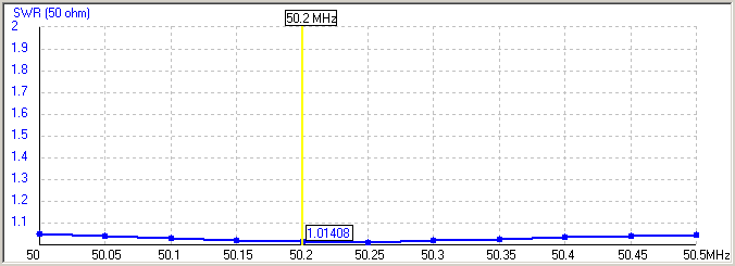
After assembling 4 antennas each one was measured - it simply shows that Pop's designs are reliable and accurate. Every of 4 antennas giving perfect response, see below.

Projected data


Measured (1 lambda above ground):

Each antenna is feed directly with CNT-400 coax cable, lenght of 5,30m calculated upon stacking distance on H-Frame, with 6 Fair-rite cores as CMC, ended with N-male connector. Home made ALsquare coax splitter was made on occassion, calculated from freeware APPCad software.
Single antenna weight without coax cable 4,65kg. 


This was the easiest part.
Now H-Frame need to be made, but how to, if You never did it before?
Well, few cups of cofee, few cigars and initial project was on the table.
Finally H-frame is made of AL pipes dia 45mm(2mm thickness) in the middle part, and 40mm pipe at ends of frame. Cross parts are 60x20x2mm profile, welded to get desired strenght, and prevent of frame saging with antennas. Of course I know this looks very "amateur" construction, but it's my first attempt to build something like that. Finally got a phone call from welding shop, that frame is ready : Overall weight 6,54kg's.


Time was running fast so no time for afternoon nap.
Next day H-frame was installed on the tower, with elevation G550 rotator. Isn't it too small for array? No, not at all, after 2 weeks I can say it's robust machine. Lifting the array up to 50 degrees, and smoothly going down. Yes, maybe it will not survive a hurricane, but who knows ?    


Another full day of work and Two upper antennas and right lower antenna in place - clearly visible that nothing more than this design can fit limited space at my property.
The problem started with left antenna - it simply don't fit into space between fence and tower...    
 
But, there's always emergency exit :-) Boom was placed where it should be and, after assembling rest of
the array, elements were added.


Done ! But did You noticed lower right Yagi is tilted? Yep, it is... I did not noticed it when antenna was 2m above the ground, this will be corrected later. Anyway measurements are just perfect !

 
 Some more pics. 

 "Beauty" - OR -

 
  the Beast ?  ;-)


First attempt to listen VK9CGJ immediately after installing last N plug resulted quick QSO, and some minutes later couple of his CQ's at 37deg elevation confirmed that project is done and running.

Addendum Oct.03.2017
Another good shot after Lance QSY to VK9X.


As always - thanks to Pop YU7EF.  Hat's off master.

73 & CU with delayed signal !

Friday, September 1, 2017

SP0OTC QSL's ready to send

As promised  before the dxp - here are the QSL's. Will ship them to Central bureau next batch.


Thanks to all who participate this short event.

73 ! 

Monday, August 21, 2017

SP0OTC #JO82XJ Old Timers Club Meeting

Polish Old Timers Club meeting gave us opportunity to activate another rare grid on 70MHz - JO82.
This will be last 70MHz grid pedition this Year, another joined one with Mek SP7VC.

Worked (no mode select) : DK2EA, DG1VL, DF5VAE, G0CHE, G3YDY, G4BWP, DD3SP, PA2CHR, PA2IP, G3SHK, PA2M, GI4SNA, PA3ECU, OK1VBN, SP2HHX, ES3RF, OH8MGK, OZ1JXY, OH7TE, OF1ZAA, OZ1BNN, SP3OCC, G0LFF, OZ0XX, G4BRK, S57A, SP5XMU, PA5Y. QRT 08:30UTC 

Operating site, room 106 :-)

 Antenna looking West, only "tree clear" direction

Mek's yellow GPS  #JO82XJ


We will be QRV under S.E.S call SP0OTC starting Friday, August 25around afternoon, and finish the activity Saturday morning hours ~10UTC.

Operation is pending now from Giewartów Palace #JO82XJ, where the OTC meeting is organised.
  
 pic source: Wikimapia.org

The station will be located behind the Palace building, only free place to put antenna, about 25-30meters  above Powidzkie lake level.
Almost free takeoff 240-300deg, but we will try other directions as well. More info/pics e.tc. after arrival.

Hope to work as many of You as we can.

GL & 73