Tuesday, January 5, 2016

Icom IC756 PRO Antenna Tuner repair

If You are owner of any IC 74x-75x family You can experience ATU unit failure.
Crackling sound from around ATU unit, or just "no tune" state could be ATU motors malfunction.
Assuming all the radio working Okay, we can do a simple motor repair described below.

Now my neighbour Greg SQ3PBA experienced this kind of failure, so we need to help him back in bussiness ;-)

Inspiration for this article was described by MichaƂ SP2XDM doing IC-746 ATU REPAIR, but all IC's having the same ATU, or at least motors so You'll see my example at IC-756PRO.

Of course anything You'll do - bear in mind your own responsibilty if failed.

Let's start with unscrewing upper and bottom cover of the radio :


Turn it at normal position and unscrew upper shield - 11 white Phillips screws. Before removing it, remember to pull out gently the speaker connector - yellow circle on the pic.


Now You can see ATU unit on your right hand - 4 screws need to be removed first. A magnetic PH screwdriver will do the job.
Note two yellow arrows, prior to removing PCB we need to desolder SO-239 antenna connectors.


Next and last step before removing upper PCB is to remove 3 flat tape connectors pulling it up.
What we can see is another shileding cover hiding main ATU PCB.
Just 3 PH screws and we are done.


Below we will find another 4 PH screws and main ATU PCB is ready to lift up...


NOTE: Remember to set Capacitor at faulty motor to it's max capacitance. This will be needed later when mounting repaired ATU motor.

Time to remove faulty motor from chassis - use mini #PH0 screwdriver.


Now You can pull the motor backward - this was the easiest part of repair :-D

After removal look carefully at motors brake nozzle position. Best idea is to use CD pen to mark the position, or use your smartphone to make picture - even better. The brake position set any other way than it was, will not let You mount repaired motor. If this happen You'll need to use force on delicate device to move it at right position. Better avoid to do so. Let's say that Your nozzle should be the same orientation as mine on the pics. It's very close to desired position.


Now we need to open the case - be gentle with force. Use flat small screwdriver or pliers to straighten 4 case hooks.
Alternatively You can try to insert flat screwdriver vertically close to the hook and lift upper cover of the motor. Tested - it's doable ;-)

If everything is well You'll see something similar :


Carefully look at the motor, notice each satelite wheel position, best to made 5-6 pics at different angles. Gently remove each wheel, one by one, and store in safe place.

Last part we need to remove is our failed part. This is a magnetic rotator right in the middle. Pull it up and You'll see why ATU was inoperate...


It seems that the reason is material fatigue caused upper plastic ring holding magnet broke and detach from magnet.
After that ATU rotate the magnet, but not the rotor.

What we need is to repait it, using small amount of epoxy glue, or any other cyanoacrylic glue.

First degrease all parts with IPA, or any other degreasing fluid, and wipe it gently with soft cloth.


NOTE - looking inside the magnet you'll see 3 dips, where rotator should fit. Same dips are located on top. This is the place where upper plastic ring should be glued.

Apply small amount of epoxy glue on rotor, and slip magnet on it, setting his position according to dips.
Remove excessive glue (if any)with soft material and after hardening time do the same with small upper ring to secure the magnet watching for upper dips in magnet.


We are almost done. Let the epoxy solidify, and after few hours ( or minutes ) carefully examine the surface of the magnet, bottom and upper ring, remove any glue marks or dirt with sharp knife.

Now all we need is to restore the motor to it's factory state starting with repaired rotor, and cooperating wheels in reverse order.

NOTE: Before securing the cover, check orientation of the main output shaft with metal nozzle. Assure that it's almost same as on my pics. Otherwise You'll have to open the cover again, or pray not to destroy the motor turning it by hand later.

Last thing we need is to secure upper cover of the motor - screwdriver with small 100g hammer or electric pliers will do the job.

NOTE - good idea is to add small drop of machine oil, or silicon grease, but just "small" drop.
After reassembly the cover don't forget to check if brake nozzle fit in right direction as marked before.

Attach the motor to ATU chassis, put again attention that brake nozzle should is positioned as on the picture, with variable capacitor at his max capacitance (closed). Secure gently two screws on the motor clutch.


That's it. Mount the PCB inside, paying special attention to all screws and shields/cables around.

Immediately after switching radio on, You'll see motors running to last remembered position.


73 & Good luck!

Sunday, January 3, 2016

New Years coffee with Janusz SQ3BKQ

This is an old local friend ;-)
A man always busier than me, stepping by for just 5 minutes to leave his radio for maintenance, stayed for long ham radio related talk at the evening :-)


And certainly he is not that serious as on the pics ;-)
Thanks Janusz, always pleasure to meet You.

Wednesday, December 30, 2015

EA6/SP7VC New Years trip to Balearic Islands. UPDATED Jan.01.2016


Updated Jan.01.2016 Happy New Year everyone !

#JM19MV 4m FSK441 LOG:

Dec 31.2015 S51DI, ON7EQ, G4BWP, G0CHE,

Jan 01.2016 S52OR,


As You probably aware, Mek SP7VC and Kasia SQ7OYL are now on EA6 sunbathing and drinking fresh drinks at +20C, which is totally opposite to WX here, winter cold with -11C in the morning.
Scary to go pee outside ;-D

EA6/SP7VC activity is limited to HF and 4m in Pollenca # JM19MV, you can see QRA with antennas around.


Aonther part of Mek's plan was to activate 4locators crossing on Minorca Isl., but this is cancelled now, due to problems with Ferry and limited time to activity.


Nevertheless If You wish to try MS on 4m, Mek will be QRV tommorow around 11UTC on 70.191MHz FSK 441 looking for any QSO.
The RIG is old good FT847 and 4el YU7EF Yagi EF0404pVC - portable, very light version made by RNZ LAB for this EA6 trip.
You can see this antenna on the pics below.
Overall complete antenna weight with mounting brackets, choke, e.t.c is just 2,15kg's.
Thanks to Pop YU7EF for his repetitive and professional antenna design.


And here is Mek himself assembling the Yagi at JM19MV.


Good luck with the QSO's


73!

Wednesday, December 2, 2015

ICOM IC-746 anti "sudden death" modification

If You are IC-746, PRO or just ICOM 7xx family owner You've heard probably that some of them, extensively used i.e for digimodes or EME can die suddenly on TX chain.
Symptoms of no TX power at all, not even a small peep, and nothing on the meter.

This issue is already known, and well documented on the web, while ICOM never agreed that it's the failure judging that ESD is responsible for this failure.
In fact, there is a chance it could be truth, but what if radio was unused on digi, worked as IF for transverter and not hit by any lightning?

Personally I am not believing in ESD case.
This 746 radio You can see below has been traveling across Europe, North America, Caribbean working under unusually stress conditions.
Field operation, humidity, thunderstorms, various mains voltage, another highpower transmitters nearby on DX-pedition - ESD protection is the last one to think of in such enviroment. And there was no such protection for sure.

Another experience with my own 756PRO3 shows, that despite changing electrical design in late models of IC 75xx to preserve such failures (as discussed on OZ2M page) Icom's still dying from time to time.
Mine died suddenly few Years back, just before big 6m opening when Jimmy W6JKV worked as V26JKV.

After replacing uPC1678 and adding a simple thermal mod, quite similar to all these published, I can say no stress anymore. My PRO3 is extensively used on EME, HF, digi and other 100% keydown modes. Nothing but adding radiator.
How many times I'd changed antenna plug on the back? How many thunderstorm it survived with HF or 6m antenna connected? Thousands, I can say.

For more info and discussion about see Bo's OZ2M page or another nice pages as OH7FES and KB6NU

My way of this mod is just another way to get the things sorted.
While in IC756PRO family RFUNIT is placed on the side of the TRX and mod can be done very simply, doing various thermal mod in 746 can be tricky because of small place around IC151.

To be continued - QRL calling :-)

Wednesday, November 11, 2015

I0QM Balun for 70MHz antenna

Another design of real balanced-unbalanced unit, this time for 4m - 70MHz band.

Previous post gave us some general idea about I0QM balun, this time some pics and "making of"
4m version.

Starting with accurate cable measuring, we need to have 1/4L and 3/4L coax lenght.
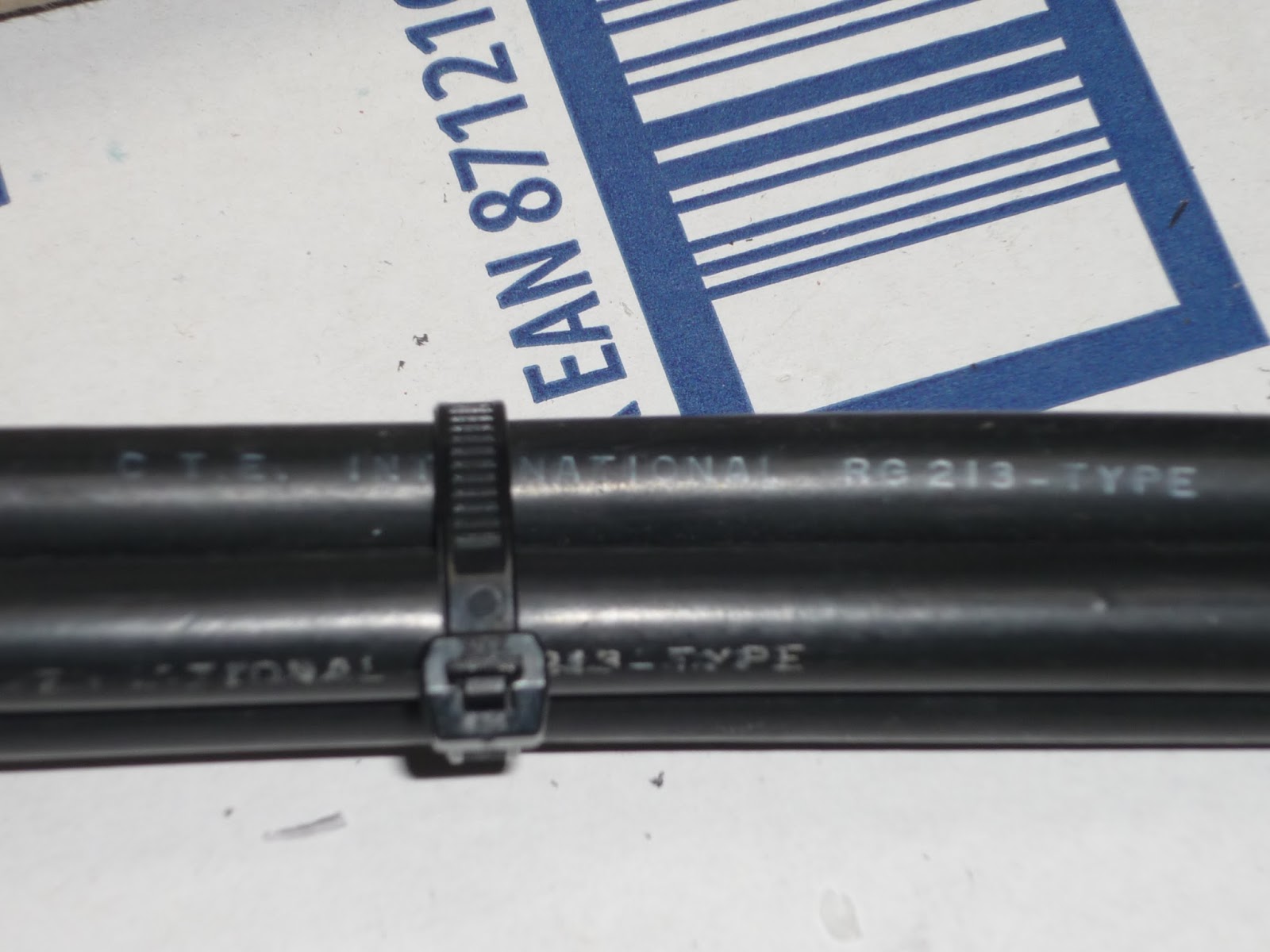
This time I have spare parts of Italian RG213 C.T.E International cable.


Slightly smaller at diameter than ordinary RG213 MIL-C type, but more flexible.
Of course another cable will have different velocity factor.
Using this cable lenght of 690mm were cut for 1/4L at 70.200MHz, giving X=0,5 Ohms at given frequency.
The other part is 3* 690mm. For those unfamiliar with coax baluns, "lenght" is a distance measured at shield of a cable,
not his inner conductor.

Before assembling the cable I did some test, here's analyzer output of SWR and RL.
Balun was terminated with non inductive 50Ohm.


Additionally small ABS box, N-F connector and ~80g of expoxy resin will be suitable for our project.


The box has needed holes drilled, one for N connector, another end two parallel holes for coax cables.
This will be output end of balun.

After accurate cutting 1/4L and 3/4L of coax cables shield were soldered each end
and slipped into box. Hot silicon glue was added to seal cable before applying resin.


Next, small piece of soldered metal pad was added to give shield connections with N connector.
Next step was adding epoxy resin to seal all the connections and make them waterproof. And the other end with soldered M4 joints sealed with self amalging tape :


Here's assembled balun, ready to use.


73 & GL!

Saturday, November 7, 2015

Another 4m DX pedition by Mek SP7VC and Kasia SQ7OYL

As You probably aware, there will be another HF/4m activity organised by Mek SP7VC.

This time EA6/SP7VC, as Balearic Islands are the target to welcome New Year 2016.


Activity will be mainly from JM19LV, city of Pollenca, but also ferry trip to Minorca Island is planned, a place where
4 sqaures JN10,JN20,JM19/JM29 are crossing. This will be field operation as always, so stay tuned for more info later.

Image credit - Ham atlas, SP6NVK, www.hamatlas.eu

Rig used - FT847 +PA GU-200 ,phased Verticals 160-80-40m + vertical 40-10m ,4el-Yagi 4m

GL all !