Websites are full with similar malfunctions in this "ol' good" rig caused
by deteriorate solder around PIN switching diodes in PA, both 2m and 70cm (see article by Peter OZ1PIF).
But there could be another cause - few OM's reported it before and some of them bring the radio back to full functionality after repair - see 2m module repair by OK2KKW guys http://www.ok2kkw.com/zzz/ft847_pa_failure.htm
This time 70cm module suffered from overheating, or (my personal thoughts ) mechanical and/or temperature stresses, after long period of use. Will back to this "probable" cause at the end.
Of course this issue can be repaired by replacing original module with Mitsubishi M67799M/A module -with no additional tuning needed.
If You are not skilled enough with ROHS soldering just don't do it.
These legs are very fragile and thin, module can be damaged easily.
Let's start - first we need to remove zillion of screws around PCB, 4 smaller screws around 2m & 70cm models also - do not use excessive force, they are glued - use good philips screwdriver instead.
After removing the PCB it's obvious that Yaesu did not use much "very expensive" beryllium thermo paste under transistors at factory stage :-), nevertheless, we will remove old, dry fluid and apply fresh one later.
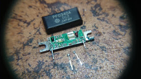
Just after desoldering first two legs the become loose, and popped somewhere. Actually they gone inside the module :-) input and output legs were still "soldered" in module. Let's see how Mitsubishi PF0340a looks inside...
That's it - opening the case with small screwdriver revealed the mystery of intermittent power - two legs - power supply and bias were completely away, looking closer to their solder pads we can see completely damaged soldering points, they are grey and absolutely not OK.
Let's prepare to the module to repair job - find some bright place on your workbench, magnifying glasses and temperature controlled soldering station, good "Silver" ROHS solder will help the job much.
For the job prapared small piece of unused PCB and double sided tape to secure the module right in place, and avoid accidental move when soldering.
Now ceramic module pad and the legs are on same level as "help" PCB.
And voila! This is the module after soldering - all 4 of legs were soldered again, just in case.
Bearing in mind that only two of 4 legs were detached, why other two IN/OUT were still OK?
My idea is that beside solder issues like crystalizing after long period of use we have another possible cause - it's mechanical and thermal stress applied to both modules over the years of use.
This is not the point of this post, but I think temperature issues (heating/cooling curves) between ceramic pad, heat spreader and the chassis could have something common with it.
An idea came to my mind to prevent it in the future - adding VERY small amoount of plastic epoxy resin just between the legs and bottom of the pad :
This will not harm the module, and possibly will prevent direct forces to soldering points at the ceramic pad.
Test after assembling the radio ( don't forget to apply new cooling paste ) show stable 50W output without any fluctuations of power.
Addendum: if Yo have the PCB removed don't forget to check PIN diodes legs. Very often they suffering deteriorate solder also - see picture. Noticed also some bad marks solder around filter coils - mechanical/temperature stress ?
Another one :
We are done - have fun with your repaired FT-847.
73 !


Witaj Greg. My radio works UFB now, thanks to your good skills !!
ReplyDeleteVy 73 de OZ8ZS Henrik